Building My Bugatti Type 13 Chassis
Sept 15, 2022
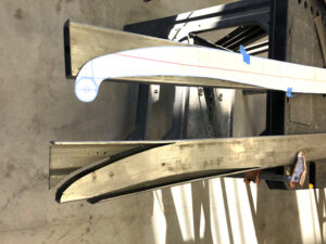
It finally begins! After nearly 6 months of exploring, purchasing parts, attending the Huntsville Grand Prix, meeting with individuals, working on two different CAD designs, and daily dreaming, I finally started the build today. I started cutting my two chassis rails. I transferred my Fusion 360 design to paper using a MAC program called Print to Scale. This simple program accepts a picture and then enables you to set a dimension between two points of your choosing and defining the dimension between those two points. Then it prints it out on 8-1/2″ x 11″ sheets taking as many sheets as are necessary to piece together the entire image to scale. Once printed and cutout to shape, its a simple matter of taping each into its proper position. The built-in guide lines makes this a simple process.
I transferred the design to the 3″ x 1″ rectangular tubing from my prints and began cutting using my new jigsaw with a new metal blade. I liked the fact that it cut through both walls so I did not have to worry about transferring the template so the top and back side matched perfectly. Unfortunately, the blade did not cut a straight 90 degree angle so the backside cut was off by about 1/16″. The new jigsaw angle retainer was not set tight from the factory so it veered off; my bad for not checking everything first!
I am leaving the top and bottom edges intact so I can simply bend them to follow the new shape. While the backside cut was off a bit, I will easily be able to recover by jigging it into its proper position prior to welding. The jury is out on whether I try the jigsaw again on the second rail or if I just use my circular cutoff blade. I’m leaning toward the latter.
Tomorrow is another day and I plan on getting both chassis frames ready for welding. I need to practice a little bit on some scrap metal to make sure I get the right welding settings and technique. I want and need for these to be solid and perfect as possible.
Sept 17, 2022
I practiced welding today using 1/16″ scrap. I decided to use the 240 volt with .035 wire. I had great success with this when welding 1/4″ steel and was extremely impressed with myself.
I really struggled to get good welds even though I used the Titanium recommendations. I kept playing with different settings, but I was not satisfied. I was tired easily today, so I put it away and decided to do some more research and try again when I felt better.
Sept 19, 2022
I felt pretty discouraged after my welding attempts last Saturday. It appeared my welds were very flat, I just did not get any piling. I learned that this had to do with the voltage setting. So today I started messing around with adjusting the voltage and refined the wire speed. Another change I made was to wear 2x magnifiers while welding, it greatly improved my visibility of the puddle.
Last Saturday, I bought the 18,000 lumen shop lamp from Harbor Freight and placed it to the side but slightly behind me. This really puts out the light and together with the 2X eye lens magnifier really helped me to truly see the puddle. This proved to make a big difference. Between the refined settings, magnifier, and lighting, I started making some really awesome looking welds! I even welded pieces with relatively large gaps. By controlling the puddle, I filled them in and made an exceptional weld.
The relief I felt of finally getting it right was very exhilarating! I had to really fight myself to work through my issues until I found the right settings and visibility. I so wanted to just get on with it. But I’m glad I restrained myself and kept exploring and practicing until I got it right.
Tomorrow I will do one or two practice runs, but then move on to welding the chassis.
Sept 20 – 27
I finally felt comfortable enough to start welding beginning with the leading curve shape on one chassis rail. One thing that Steve Vinson pointed out in one or more of his video builds was to not overheat the chassis by welding too much at one time to prevent the warping of the metal. In my enthusiasm, I simply could not restrain myself so I happily welded on. I did in fact begin seeing some tendency to warp, so I had to slow down and also keep the piece clamped down and allow it to cool off. This is a new discipline I will need to develop for sure. Once you finally get to weld, it’s really hard to stop, it is just so much fun and I want to go race!
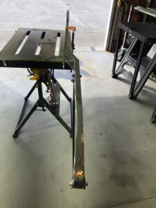
The more challenging part was the end structure that captures the leading edge of the elliptical spring. As the spring is 1.25″ wide and the chassis rail to which it attaches only measures 1″wide, I had to build up another 1/4 inch. I did this by building and welding 1/8″ plates with a pleasing curve shape to either side. I then welded them to either side, and also welded 1/2 of 3/4″ pipe to capture the spring. I also welded 2 large size washers at the end encapsulating the pipe ensuring proper alignment and that the spring could easily be inserted and removed when needed. It was a bit challenging especially when it came to grinding to get a pleasant shape. I learned by trial and error, I had to grind the perimeter of the weld first to get the desired shape and then work on the tapered angle. Another invaluable lesson learned. A little more welding and grinding and it will be presentable. The second chassis rail will be a lot easier given all that I learned on this first one.
I found cutting the 1/8″ steel curvey side pieces with my new portable jigsaw doable, but also challenging. Its small size and curvy shape made clamping it to my workbench impossible in many areas that needed cutting. So I had to use the grinder and cut-off wheel to cut a lot of it. Oh, if only I had a good bandsaw!
My little 10″ Craftsman saw can work for thin aluminum with patience, but for work like this, I really needed a proper metal cutting bandsaw, but they cost $1600 and more!
YouTube to the rescue! I discovered several people including Adam Savage from Myth Busters who all had the same dilemma as mine. Their solution was to buy an inexpensive portable bandsaw and build a little table to hold it upright. The portable bandsaw’s 1/2″ blade, power, small size, and low cost fit my needs perfectly.
So I drove to Rexburg and bought a portable bandsaw from Harbor Freight for $129 as my local store did not have one in stock. A pair of blades ran another $16 and now all I need to get is a 1/4″ steel plate. I’ll either use my stock of 1.5″ square tubing or buy some 1″ square tubing to build the frame. So that will be my next project before I continue building my second chassis rail.
Before I left to Rexburg, I did cut the chassis rail in two places to make the jog in the rail to widen it per my plans. I chose to cut three sides of the 3″ x 1″ rail and bend the remaining side to get the desired angle rather than cutting off the entire piece and welding the entire unit back together.
I discovered I needed to measure the desired finish angle, which was 10.5 degrees, then cut a notch that was 10.5 degrees to the left and right of the bend line. By measuring the angle carefully and using finely drawn lines followed by precise cuts via my grinder’s cut-off blade I acquired the exact angle I wanted. The remaining attached side bent very easily and by clamping down the rail to my welding table and double checking the angle and squareness, I was able to tack weld the piece back together perfectly! I was most pleased with the result.
My last cut will be to jog the rail vertically by several inches, but I want to review my design before I do. I fear my current layout is not quite right, so I am going to investigate and research this a little more first. So that will be a good side project as I build my portable, vertical, benchtop bandsaw.
Oct 1, 2022
Wow, it’s hard to believe that two weeks have passed since I began building the chassis rails and I’m still not even halfway through! But I am making good progress and I feel very good about the build and overall quality. It’s far from perfect, but good enough I will not be embarrassed when others look more closely.
Most importantly, I am learning a great deal and my welding is getting better. I am definitely getting a better feel for it and am able to change the welder settings on the fly to accommodate changing conditions. So that is good. The secret for me was adding a lot of light from behind, wearing 2X magnifiers, and watching the puddle so I can control the weld. Seeing the puddle clearly made all the difference in the world! Before I really focused on the puddle, I was focused on the leading edge but that really left me in the dark. Focusing and seeing the puddle so you can control your gun is where it’s at. I’m not sure why it took so long to figure that out!
Today, I bought a 2″ bi-metal hole saw blade (along with 13 others sizes in a kit from Harbor Freight) so I could drill out a hole to accept the 2″ diameter tube for the mock-up rear suspension. My drill press is wobbling, so that’s my next project to get it fixed and true. But it was good enough to drill through both sides of the 1″ wide rectangle tube.
In examining the chassis vertical jog at the rear wheel position on the real Brescia design, I observed the vertical displacement was far less than I had in my Fusion 360 design. I also recognized that the last couple feet of chassis rail height where less until the very end when the torsion tube goes through the chassis rail. So I modified it significantly so it now mimics the real design. Now the rail transitions from 3″ height to 2″ until the very last few inches where it goes back to 3″ again.
I configured it so the 2″ rail overlaid on top of the 3″ rail for about 6″ to increase strength then tapered each at about a 20-degree angle. The appearance matches the real car and I feel it will be very strong.
When welding this, I secured it tightly to the welding table to assure flatness and good alignment and took a lot of time spot welding sections and moving to other sections to control the heat to prevent warping. This strategy worked very well even though it took much longer.
As for why this one rail took two weeks to build. Well, I took three full days building a small benchtop bandsaw so I could cut steel better. See my Pitstop blog where I covered that project.
I also don’t work in the shop on (two) Sundays, plus another two days on preparing the house and boat for winter. So in all reality I’ve got about 8 days including runs to the grocery store, city dump, doctor, dentist, and church activity. I hope to build the second railing in 3-5 days.
To finish this railing I need to add two small pieces of 1/6″ steel for transitions. There is also some more welding, but I am going to wait until I assemble and weld the entire frame before that.
That being said, it’s time to order the rear Peerless differential and design and build the front axle. Most cyclekart axles are constructed from round tubing, particularly chromolly .095 wall x 1-5/8″ diameter. I am using mild steel 1.5″ square tubing with 1/8″ wall.
The advantage of the round tubing is you can easily adjust the castor to any setting as often as you like. The square tubing design either means I need to weld the axle uprights on each side to the desired castor angle of 5-7 degrees or make it so I can still firmly attach the square tubing to the elliptical springs using some angled spacers. I chose the square tubing as I thought it would be easier to construct; however, I did not account for the castor angle. I am going to think this through very carefully.
I also need to get the wheels prepared by grinding or machining to accept the hubs.
So these next projects will be good to begin as I build my second chassis rail.
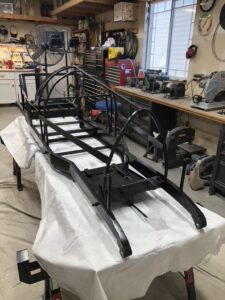
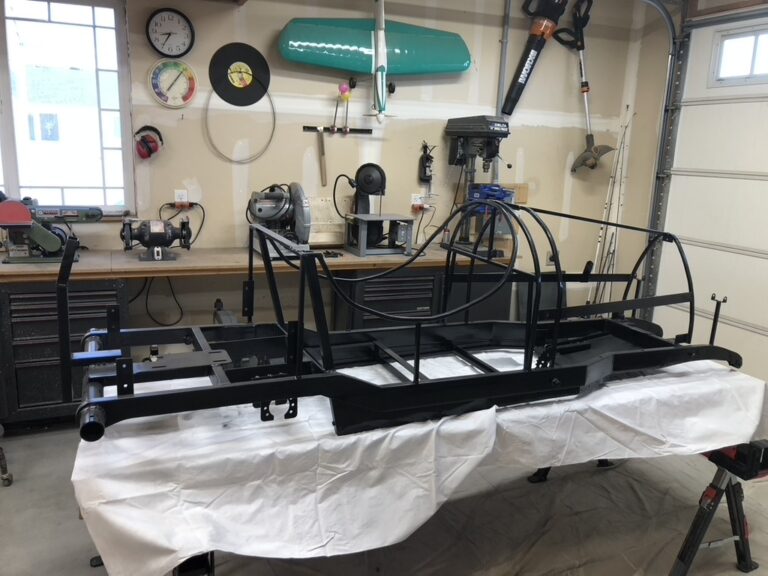
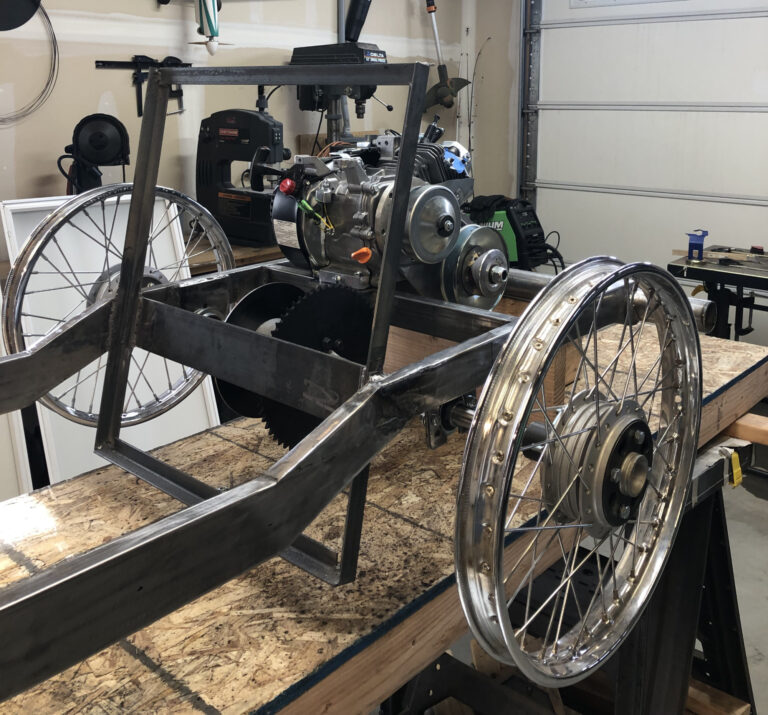
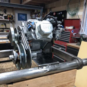
Chassis staring to really come together. Mocking up the motor placement and mounting.
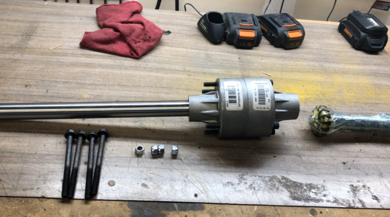
A simple trick made quick work of assembling the differential, but I had to figure it out first.
Oct 22
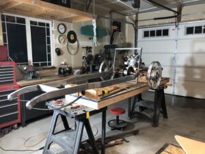
Holy cow I thought I would never get the second chassis rail built so I could marry them together. But this week it started to happen. I finally got the second chassis rail built carefully comparing it to the first one and even clamping them together to ensure alignment and perfect symmetry. Once the second chassis was completed, I built a small table top that are supported across my saw horses. I immediately noticed the warping and misalignment between the two chassis rails when I began bridging cross pieces. So unfortunately some major surgery was required.
I recognize now that had I started with a square and true table and built a jig that things would have been so much better. I thought I would save time, but I ended up spending a couple of days trying to make things right, so it would have been so much better to do it right to begin with. Lesson learned for the next complicated frame.
I stopped further work on the chassis, I figured I needed some 3″ x 1/4″ flatbar to make my engine compartment work the way I wanted, so I have to wait until Monday morning to buy some. In the neantime, I am awaiting arrival of my Renegade front axle. Once installed, that will determine the fitment of my rear axle and all the supporting weldments. So I hope it arrives this coming week.
Today I assembled the Peerless Differential that came in two parts. I was worried that in taking it apart I would muck up the complicated inner workings, but this turned out to not be true. The interior mechanicals was actually extremely simple and after a couple of missteps, I figured out how to build a simple jig to reassemble using gravity. Here is my Peerless 100 assembly blog on the assembly including a video. It might help others when they need to assemble theirs.

Nov 4
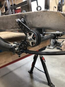
I received the front axle and the larger brake disc this past week, so my frame is really taking shape. I had to extend the engine mount plate purchased from Renegade to bridge the full distance between the cross member and the rear fake suspension tube. I also decided to use 1″ angle to build the seat back frame and make it an integral part of the frame. This strengthened the frame where it changed elevation and allowed me to use flat 1/4″ bar to weld other rear axle supports with bearings. I still need to build those. But this construction method gave me more space between the seat back and axle sprocket.
The cheap Chinese type torque convertor would not mount in the desired 10:00 position as the chain interfered with the convertor’s backplate strengthening ribs. I would have had to grind them down by more than half which I thought would be problematic. By rotating it to the 4:00 position, the chain has a straight and clean shot between the convertor and axle sprocket. I am using a 10 tooth drive sprocket and 60 tooth axle sprocket with the heavier 41 type chain.
I have decided to build the seat back and floor pan out of composite using high density foam and either fiberglass or carbon fiber. As winter has hit again, I cannot keep my garage temperature above 60 degrees with my heater so I will build a little insulated box with a separate temperature-controlled heat source to cook the parts after I have laid them up.
One surprise was the front axle spindle elevation. I had assumed it would be close to the mid point of the 3″ high rectangular tube, but it was closer to about 3/8″ from the top of the tube. As such my rear wheels are a little more than 1″ higher than the front now, but I don’t think that will be bad. I can still mount the axle below the front suspension spring which is the way the Type 13 Bugatti’s were built. But I will keep it mounted above the spring for now.
At this point I only have to cap off a chassis cross member at the front of the car and the chassis is done. It sure took me a lot more work than I ever imagined. I would not recommend this to a beginner or anyone with limited time at hand. But for me, it was alright because I got a more authentic look and learned a heck of a lot in the process.
February 2023
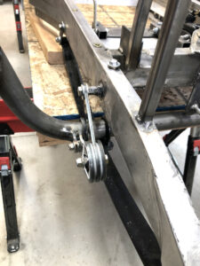
Renegade Cyclekarts announced their new friction shocks in December 2022. The Bugatti Type 13 used these and I had planned on building a set if I had time. I was most delighted that Renegade made these available so I immediately bought one set. They promised delivery in Feb and true to their word I received it early in Feb.
Steve Vinson did a video showing how he installed them on the club cyclekart project so I did mine the same way. It turned out quite good and I was very proud of the installation. They do seem to dampen the front springs quite well too.
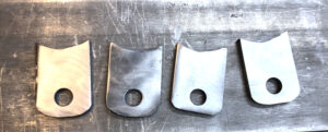
The shocks do not come with mounting tabs (as Renegade openly noted on their website), so I built my own. Steve Vinson had purchased items from a hardware store with inserts and then modified them. But I chose to simply build my own. Once I had all four roughly cut out, I stacked them all together to do the shaping so they all were identical.
April 2023
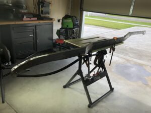
At long last I had all the welding, forming, holes drilled, and beating into shape completed. It was finally time to paint!
I chose Krylon Fusion rattle can paint as it was the primer, color, and clear coat all in one easy stage. All the prepping and painting took less than one day and I was pretty pleased with the end result. There are a few places where the paint went on too dry, but overall it looked really good.
Oh, it felt incredible to gaze upon something that really looked good! It was a great feeling to have finally reached this point, but there was still a lot more to do so back to work.