Type 13- Body Framework
Nov 19
I’ve been looking forward to building the body frame for a long time. I plan on using 1/2″ square steel tubing and welding it to the chassis.
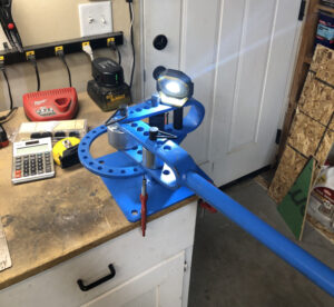
This would require acquiring a small tube bender and learning how to use it. The one from Harbor Fright was not to my liking as it was floor mounted and it did not appear they had a benchtop mount model any longer, so I found a Mophorn YP-9 for $70 on Amazon. The unit was just fine except the extension handle did not slide into the main arm at all. I had to do some serious grinding and sanding to get it to slide in as needed. Otherwise, it was perfect and I was pleased with what I received.
Learning how to use the bender was another thing. The instructions that come with the unit are barely sufficient to assemble the unit and do not touch upon its use. Given all the dies, and other bits, it can be somewhat overwhelming initially. It was YouTube to the rescue once more. Save yourself some time, simply watch this video. In principle, it’s actually not that hard at all. But like everything else that’s unfamiliar, you just got to dive headfirst into it and learn by doing.
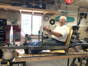
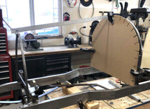
I began my body frame build with the main support structure for the instrument panel. I took the liberty to sit in the car and make some motor racing noises just to be sure the placement was correct.
With a cardboard template in hand, I cut my first 5 foot piece of 1/2 square steel tubing and proceeded to apply what I had learned from the aforementioned video as well as one recently posted by Dennis Thomas covering the build of the club cyclekart. He informed us to make one inch incremental marks and then take it easy. I was super cautious and was pleasantly surprised when I had the first half done within about 10 minutes! What a thrill, I was already an expert at this. This wasn’t hard at all.
And that’s when the real learning came into play. My over-confidence led me to over-bending in several places on the opposite side. So I spent a lot of time trying to correct this by sheer arm force, stepping on it, squeezing it on my bench-mounted vice, and finally in frustration beating it with a rubber hammer. What initially took me 10 minutes turned into many hours for the second half. Even so, I still did not have a perfect fit plus I managed to get a twist into the part as well!
It was at this point of rage and madness, my poor unsuspecting wife stepped into the garage to ask if I wanted dinner only to have her head ripped off. Needless to say, I had some serious apologizing to do during dinner.
After dinner, I settled down, relaxed, and reconciled myself to taking my time to fixing it. And about 1/2 hour later I had it very close to finished. It was getting late, so I hung it up for the day, but I learned how to take out or reverse the bends on the bender machine which proved so much easier than the brute force method I was applying.
Tricks I learned were:
- Be patient and move slowly
- Adding a small light to the bender so I could see my 1″ incremental marks more easily
- Applying a very small piece of masking tape to exactly point to the marker point I needed to bend next so I did not get confused once the piece was in the bender with all the other 1″ marker points
- Turning the part over and unbending any error or excessive bends was super easy. I don’t know why I thought I had to reconfigure the machine to accommodate that. I did; however, have to rotate the bender machine on my workbench to provide the space needed to accomplish the reverse bends.
By applying these little tricks and exercising patience, all went far smoother. Once I get relaxed, I find this very enjoyable and satisfying. At the end of the day, it’s very gratifying to be learning something new, overcoming fear of failure, and developing a new skill.
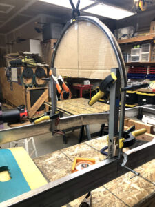
Once I had the top curve corrected and fitting I welded on support pieces so it now is quite robust and looking like the real car. I must say, I was most pleased with the outcome.
Dec 7
Other duties and home projects resulted in a slowdown on my Bugatti project; never-the-less, I steal a few moments when I can to think through how to best proceed.
I will add a secondary fuselage member about 4 inches forward of the instrument panel to add greater overall body strength and support plus capture the front hood cover. I have already mounted the front radiator, so now I need to loft the dimensions of the secondary fuselage station by running lines across each connecting point. I am contemplating using a laser pointer to accomplish this but I need to figure out a simple means of attaching the pointer in the right manner to accomplish this. It should ne be too hard, but it will take a little creativity to figure out how.
The front hood will be hinged across the top of the car running longitudinally from the front radiator to the secondary fuselage station. I will cut the hinge in several places so it can be bent and attached to 1/2 tube welded into place. This idea, perhaps unorthodox, will give my hood the support it needs while permitting both sides of the hood to freely open and shut.
I will also bend and weld some more pieces of 1/2″ tubing along the cockpit sides. This has a generous curve in two directions, so I will either need to learn how to accomplish this or do it in two pieces then weld them together.
I am also using cardboard to create templates for the fuselage aluminum skins. This has been immensely helpful and allows me to see how best to construct each piece.
Feb 4
My Bugatti project has been mothballed for two entire months while doing a major remodel of our living room. So it’s time to get back to framing.
I decided to frame a forward fuselage bulkhead to mount the fiberglass radiator. To match the complex shape of the radiator, I initially thought it would be too difficult for me to bend it all in one piece so I decided to make cuts in the 1/2″ rectangular tube every 1/2″ to enable me to bend it more easily. I then welded all the cuts and ground it down. This took an enormous amount of time and when I finally got it welded, the overall shape had shifted enough to where I had to go back to the bender anyway! So I chucked nearly two days work into the metal trash bin and started over.
In my second attempt, I decided to bend two pieces that could be joined and welded at the top. In the process, I really refined my bending process immensely to where I now consider myself darn near an expert.
Rather than marking and bending every half inch, I chose to only make marks where bends needed to be. This eliminated the confusion of bending at the right mark when positioning the metal in the bender.
I also learned to make the mark on the outside of the bend, never on the inside nor top of the metal piece to be bent. This easily lets you position the piece exactly where you need to bend it on the die.
I furthermore learned to always bend towards the feeder side not the side already bent.
Finally, build a jig so that when you place your piece up to your template, the starting end always is positioned precisely in the same place. This saves time and enables you to ensure you fit your piece to the template very precisely.
Sounds stupid simple, but using these four simple tricks resulted in perfect bends.
Through a lot of trial and error, I finally found a technique that helps me to master this important skill when building the frame pieces.
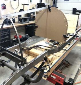
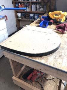
For the secondary fuselage member I needed to determine the shape as it would be different given the rapid transition of the forward cowling as it narrowed to fit the horseshoe-shaped radiator. To accomplish this, I positioned a piece of cardboard 2 inches ahead of my instrument panel fuselage member. I initially cut and shaped the cardboard to about an inch larger than instrument fuselage station. Then every few inches, I cut a slit about three inches in length perpendicular to the edge. With the cardboard positioned correctly ahead of the instrument station, I next took a straight edge and laid it across the instrument panel fuselage and the radiator along each slot on the cardboard. Then I marked the cardboard where the straight edge intersected the cardboard. Once all the marks where made, I took and gently bent the straight edge to fit the curve created by the marks and drew a line. This worked out real well.
For this fuselage station I decided to not go with the 1/2″ rectangular tubing, as I had to join two outer skins with different elevations. The body piece would be at one elevation, but the removable cowling needed to be 1/8″ lower to accommodate the leather seal and the aluminum skin.
To accomplish this, I chose to build two 1.5″ x 1/8″ flat metal pieces together, with one on top of the other to create the change in elevation.
I quickly realized that bending flat stock was a bit different than the 1/2″ rectangular tubing as it was too easy to make sharp bends. So I built a full size buck 1-1/2″ thick. I initially thought it might be possible to simply pound the flat stock into shape around the buck, but I quickly gave up on that idea. So it was back to the tubing bender with a slight change of dies, I was back in business bending the flat stock. Now employing the latest techniques, I found it easier than ever to bend to a buck than a cardboard template. It also allowed me to do a little pounding with a large size hammer to fine tune the shape to make all the transitions perfect smooth.